
The bootcounter is initialised in (line 82) with RTC_DATA_ATTR int bootCount = 0 After each hard RESET the boot counter will be reset to 0.Įach time the setup() function is activated the integer bootCount is increased by 1 (line 136). The boot counter is a variable that keeps track of the number of times that the setup() function (line 125) has been passed since a system reset.

This is done in the paragraphs below, with the relevant lines of the code given between brackets. Some parts of the Sketch deserve some additional clarifications. The yellow marked text is user and application specific and depending in the specific user settings in the code.Ģ.5 Aspects that require further clarification The reason for the resistor divider is that a GPIO pin of the ESP32 can accept a maximum of 3, 3 V, whereas the 18650 battery (nominal voltage 3, 7 V) at 100% charge provides 4, 2 V as output. To monitor the charging status of the 18650 battery an analogue GPIO pin of the ESP32 is used to measure the voltage across a resistor divider network connected to the + of the 18650 battery. One 5V output is used to supply the ESP32 (Vin) and another 5V output is used for the stepper motor driver. The battery management system from this battery provides 3 * 5V output at 2 A each and also 3 * 3, 3 V. This battery is charged in daytime by solar energy, while at night the energy from this battery is transferred to another 18650 battery via a step-up convertor (from 3, 7 V to 5V. The power supply is provided by a solar panel with built-in 18650 battery. The electronic design is shown in the following circuit diagram. The following materials are used for the Fish Feeder: See Things The complete system is contained in an IKEA food storage box that is closed with some clamps on the cover.Īfter removing the cover, a power switch is accessible and a USB cable can be connected to the ESP32 for replacing the software with a new revision if needed.Ī blue LED is installed to indicate the status of the Wi-Fi connection with the AP. The 7 mA in deep sleep are probably due to the on-board red LED of the ESP32.Ī number of mechanical parts are 3D printed.
#Fish automatic feeder full#
During full operation with the stepper motor turning some 320 mA are drawn from the battery. Measurements performed to the operational system show that during Deep sleep there is (still) a power consumption of 7 mA. The driving lines to the stepper motor are switched low after the stepper motor has done its job. For instance, the system is put into a “deep sleep” mode with only the built-in real-time clock (RTC) working. Since the system is powered by a solar panel, provisions have been made to save on battery energy.
#Fish automatic feeder driver#
A blue LED for indicating the Wi-Fi connection statusĪll electronics for power supply to the MCU as well as stepper motor and its driver are built inside the fish feeder housing.

#Fish automatic feeder manual#

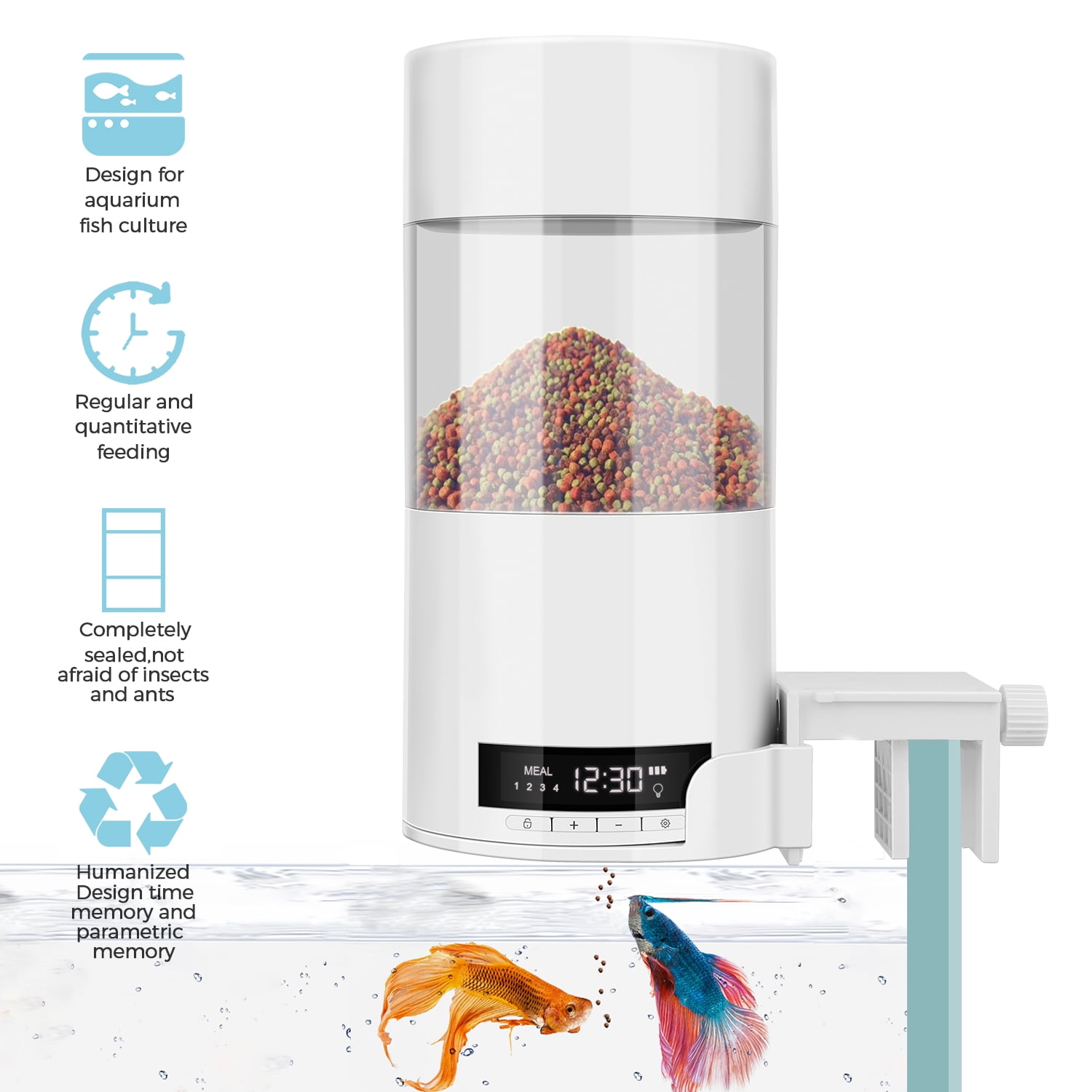
The silo storing the food with IR sensor.The Stepper Motor driving the worm in a piece of pipe.The Solar panel with built-in 18650 battery.The system, basically consists of the following main parts:


 0 kommentar(er)
